G1000: autopilot navigation and ILS approach
The Garmin G1000 is widely used in general aviation and is often found on MSFS aircraft. There are highly technical manuals online for using this GPS, but nothing on the "in-flight" management of the ILS approach, which allows you to land automatically by taking control (stopping the landing gear) only a few hundred feet from the runway (decision altitude).
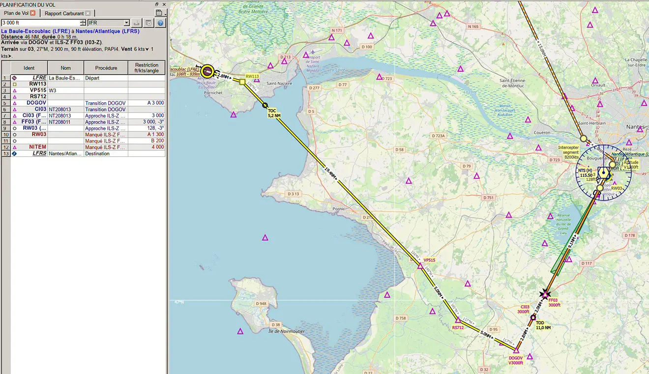
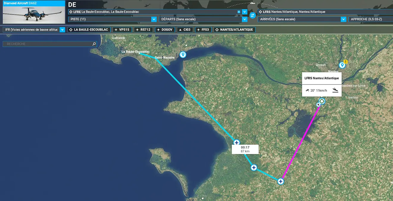
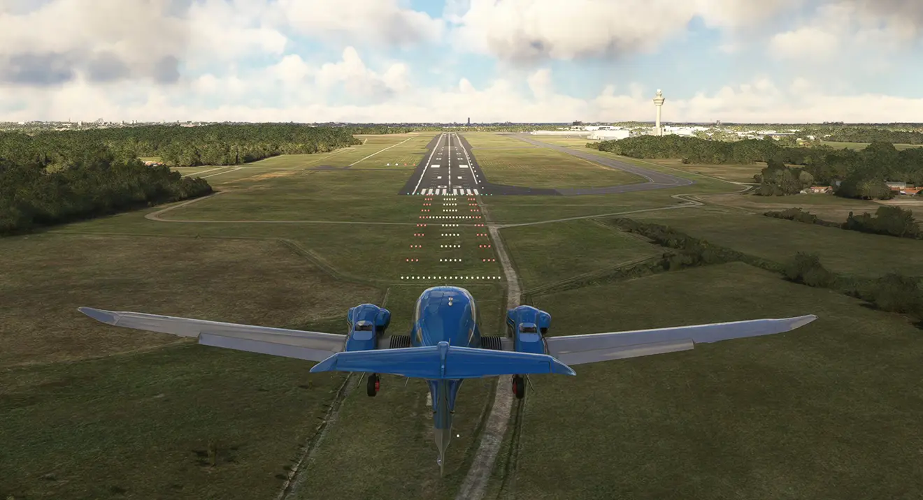
For this tutorial, we chose an approach on ILS 03 from Nantes Atlantique (LFRS), departing from La Baule Escoublac (LFRE) on runway 11. The aircraft is the Asobo DA62.
1 - Reminder: Preparing the Flight Plan and Approach
The flight plan has been saved in PLN format, which can be used directly by MSFS. We'll now load the flight plan into the MSFS world map (Space – Plus button at the bottom left).
The flight plan will then be automatically loaded into the G1000 GPS. The ILS frequency (here 109.90) is automatically loaded into N1 (LOC1).
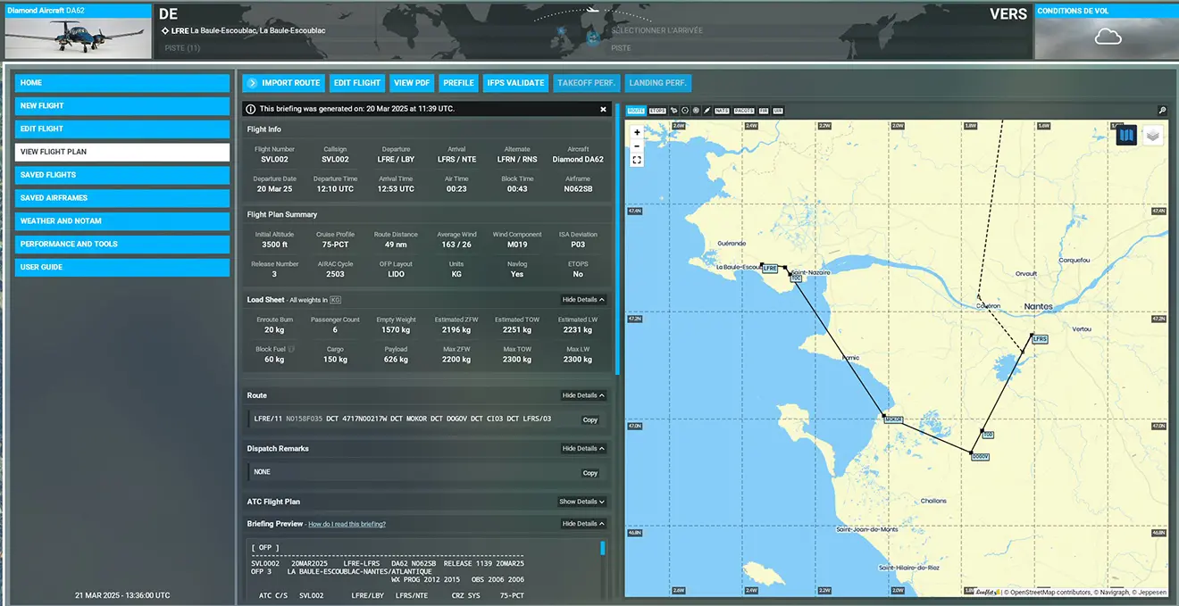
Note: You can also, of course, use SIMBRIEF to load the flight plan (IMPORT ROUTE button).
Reminder: The G1000 comes with two non-touchscreens:
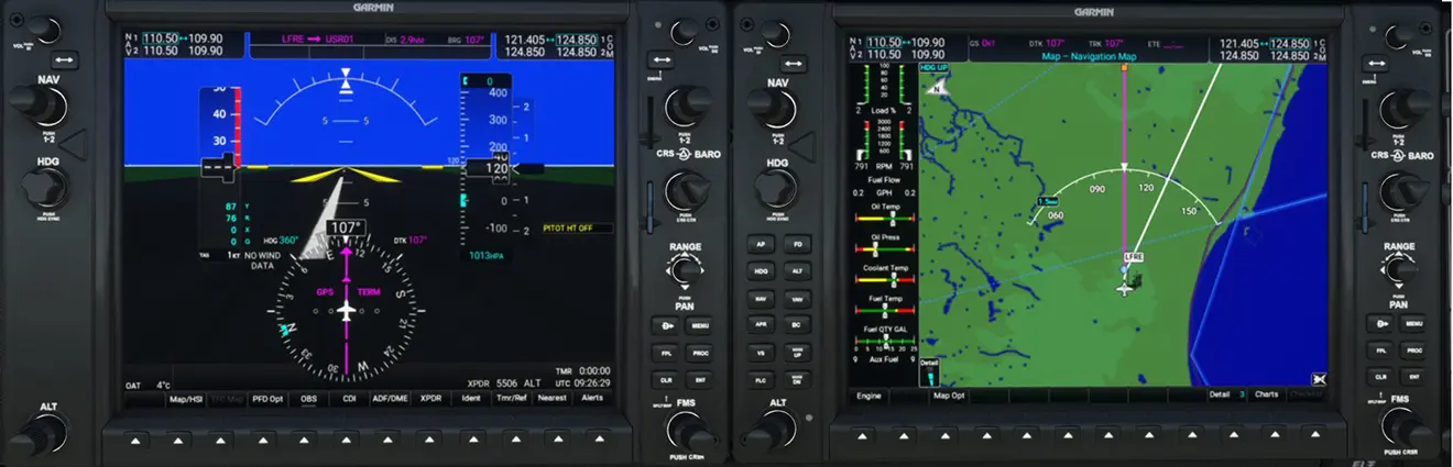
The left one (PFD) is used to manage the flight and frequencies (communications, navaids), while the right one (MFD) manages the flight plan and autopilot
and displays the scrolling map with the flight plan plot, aircraft positioning, and TCAS alerts.
When the aircraft is ready, the flight plan is already in the right G1000. You can see it by clicking the FPL button.
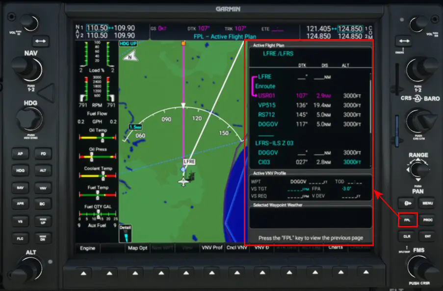
Note: We will not repeat here the manipulation of the G1000 buttons and rotary switches, which is explained in another tutorial: https://www.simvol.org/en/articles/tutorials/load-flight-plan-garmin-g1000
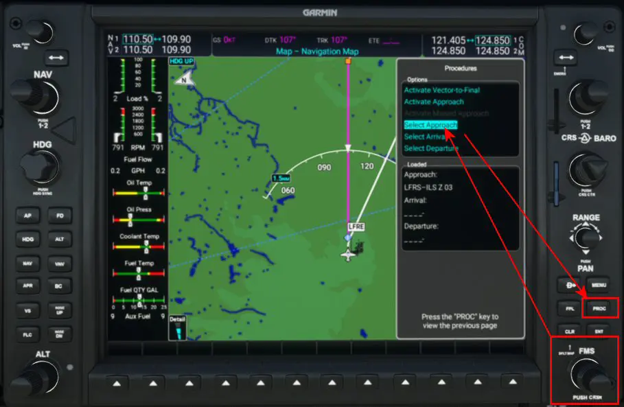
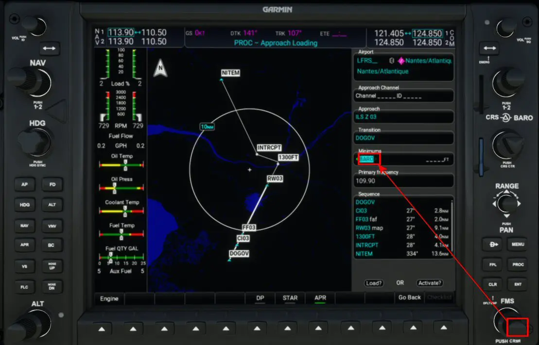
Press the "PROC" button to select the "Approach" function using the right FMS rotary switch and confirm with the ENT button.
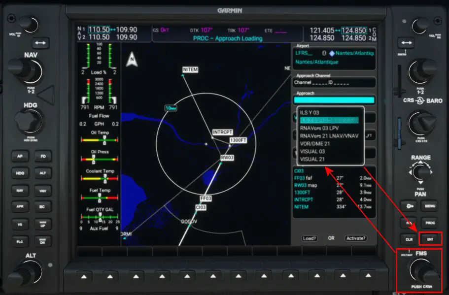
The chosen approach (FMS rotator) is the ILS Z 03.
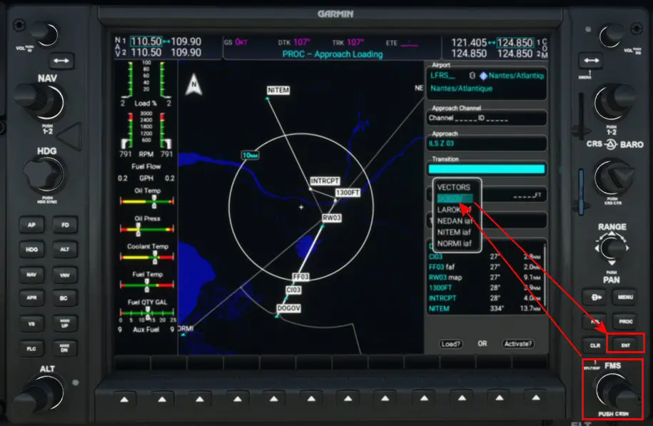
The transition is DOGOV.
You should also look for the DA (minimum) value indicated on the approach chart.
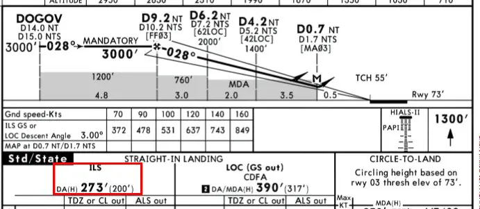
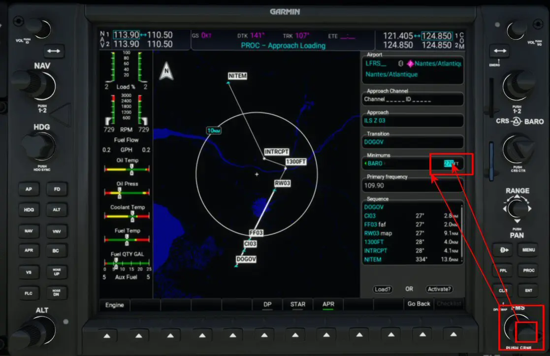
The "BARO" value is displayed using the small crown of the FMS rotary switch.
We load the number indicated on the map (here 270) by moving the cursor with the large dial and displaying the values with the small dial of this FMS rotator.
We will now load this approach by going to LOAD with the FMS rotator.
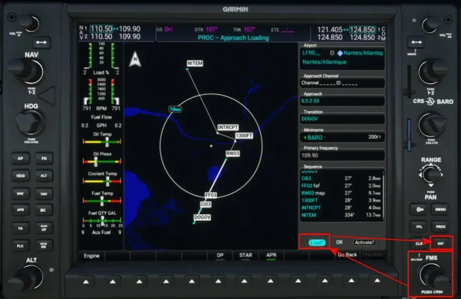
Ignore the following message by pressing ENT.
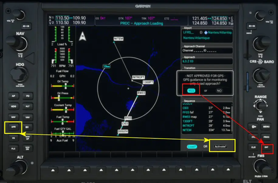
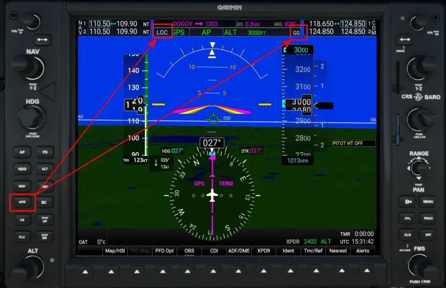
During the flight, before reaching the start of the transition (DOGOV in our example), you will need to activate the flight plan's approach mode (ACTIVATE in the yellow box on the right of the image above), then initiate approach mode by pressing the APR button (yellow box on the left in the image above). The display at the top of the left screen (PFD) will indicate in white that LOC and GS modes are armed. It will automatically switch to LOC mode after passing the procedure entry point (here CI03). If this switch does not occur, you will need to press the PDF's CDI button to switch to LOC1 mode (green directional arrow display). The following paragraph implements this process.
2 - Flight and Approach
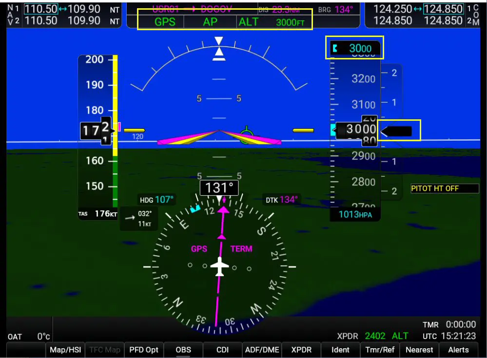
Upon takeoff, during the climb phase, we switch to GPS (CDI button) and autopilot (AP button and magenta display on the left screen). Of course, we had to enter the chosen flight level (here 3000 ft because the flight is very short and this is the entry altitude for the chosen transition) and the climb speed (here 800 ft/min). We switch to GPS mode (NAV mode on airliners) by pressing the corresponding button (gear and flaps retracted). The AFCS status box (yellow box at the top of the screen, equivalent to the Airbus FMA) allows you to control the flight plan and current parameters (in green for active ones and in white for armed ones).
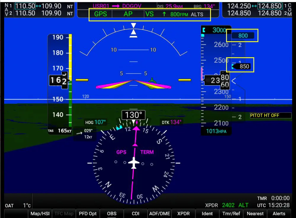
Established on cruise, we have the following stable information:
Shortly before entering the transition (here DOGOV), we will activate the approach in the flight plan,
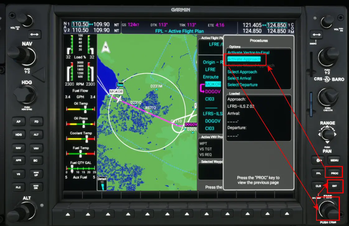
Then we'll put the PA into "Approach" mode by pressing the "APR" button on the right screen, which will display the LOC (ILS horizontal guidance) and GS (ILS vertical guidance) indications in the AFCS. These indications are in white because they are not yet active but armed.
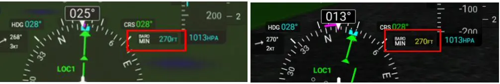
Upon passing the approach entry point, the G1000 (left image) automatically switches to LOC1 (right image); otherwise, you must press the CDI button on the left screen to switch the heading indicator to LOC1.
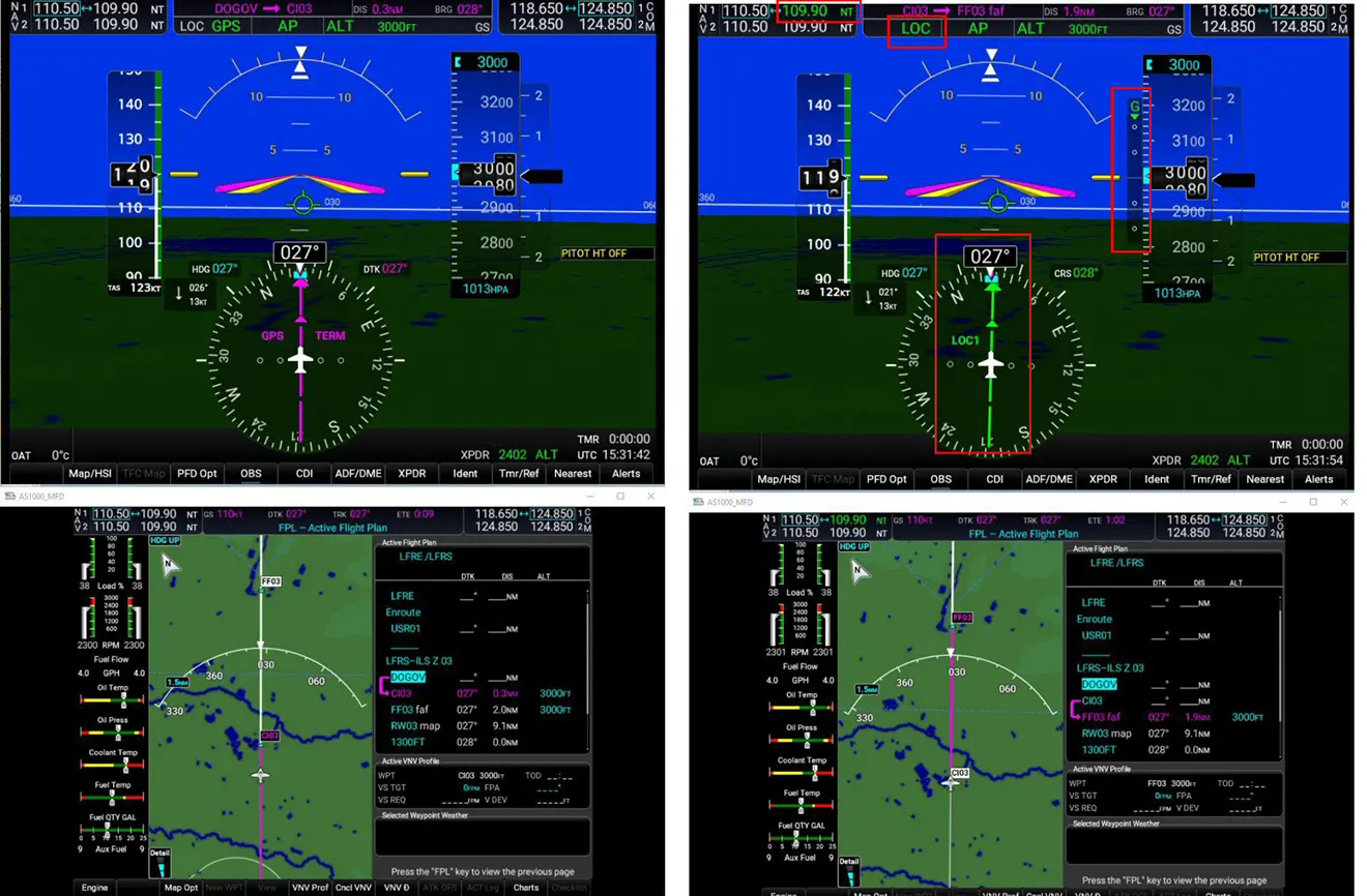
In the AFCS (top line of the left screen), LOC has changed from white to green and replaces the GPS indication. The vertical bar "G" appears to the left of the altitude scale. The green diamond will descend as you enter the ILS cone and approach the entry altitude of 3000 ft.
Note that when switching to LOC mode, the ILS frequency (top left of the left screen) turns green.
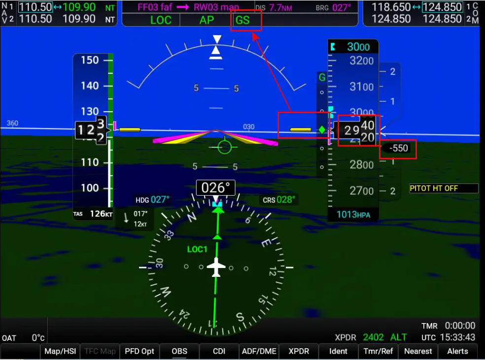
When the green diamond in the G column reaches the yellow line, the glide path is automatically downhill, and in the AFCS, GS turns green instead of ALT (it flashes for a few seconds).
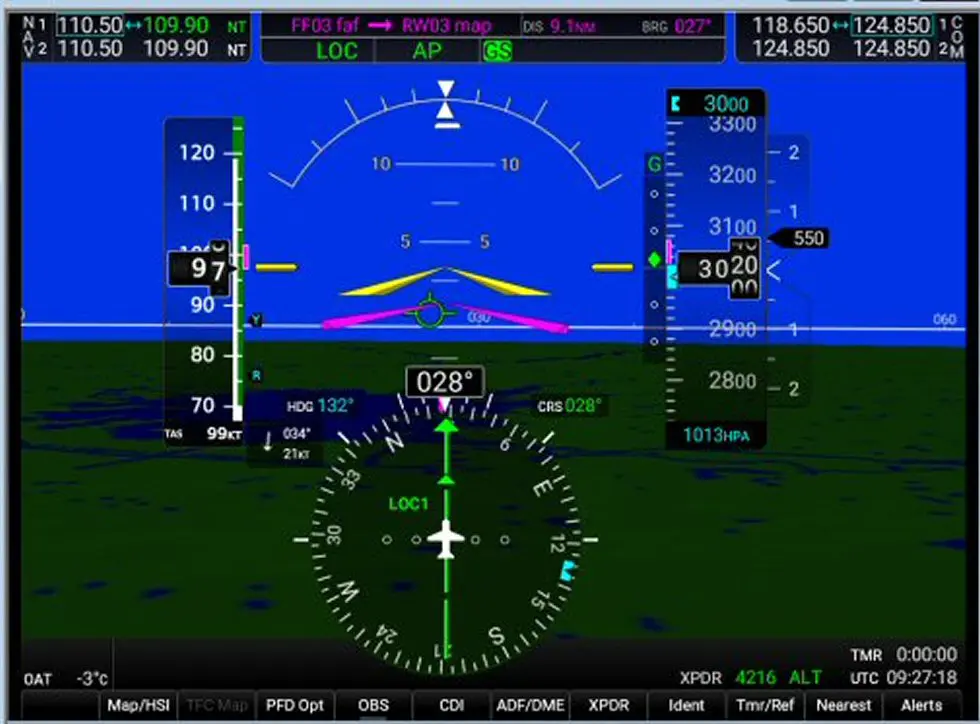
The glide descent begins with a standard 3° (5%) gradient.
The approach is operational. All that remains is to adjust the aircraft (speed, flaps, landing gear, missed approach altitude) and disconnect the autopilot at the decision altitude (DA value entered during flight preparation) to land manually.
If you entered this decision altitude during approach preparation (MINIMUM indicator in the G1000), it will be displayed in blue before the approach and will change to white, then yellow when it is reached.
Glossary:
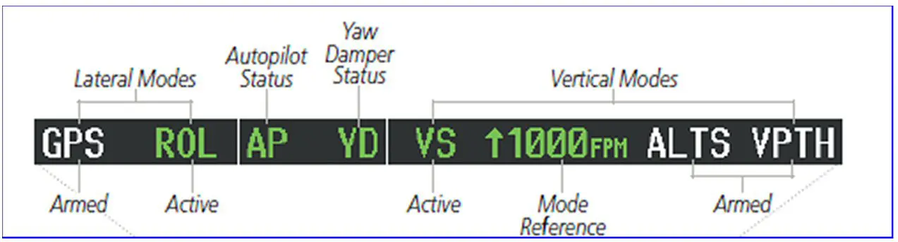
- AFCS Status box (Automatic Flight Control System): displays information from the FD (Flight Director) at the top of the PFD.
Display example (source, G1000-DA62 documentation:
https://static.garmin.com/pumac/190-01895-00_A.pdf page 417 and following).
- PFD: Primary Flight Display, a screen that displays all flight information (altitude, VS, speed, heading, waypoints, etc.).
- MFD: Multifunction Display, a screen that displays technical data (engine, fuel, etc.), the flight map with the aircraft's position, the flight plan, procedures, etc.